Powers the main TSUMV59 microcontroller and the SPI Flash memory IC.
If you need help tracking down a specific component, please tell me:
Locate the fixed inductors and linear low-dropout (LDO) regulator ICs (such as the standard 1117-series regulators) distributed near the central processing zone. Measure the output of the 5V buck converter.
The board operates on a primary input. However, the onboard components (chips, memory, and logic circuits) require lower operational voltages. The schematic details how the 12V rail is stepped down using DC-to-DC buck converters and Linear Regulators (LDOs):
This usually indicates that the processor is getting standby voltage but cannot execute code.
Powers the audio amplifier chip and the panel backlight inverter circuitry.
Adjusts brightness by modulating the duty cycle of the backlight power. GND: Ground return path. Common Troubleshooting Scenarios Using the Schematic Suspected Component Block Voltage Check Point Fix Action Dead Board (No Standby LED) Power Supply Block Check 12V input fuse and 5V/3.3V regulator outputs.
: Backlight Enable signal sent by the main processor to turn the lights on or off.
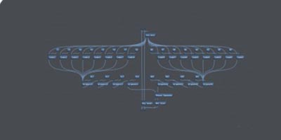
The T.VST59.031 schematic diagram is a technical blueprint that offers a detailed visual representation of the internal components and circuitry of a specific electronic device. This diagram is a crucial tool for engineers, technicians, and electronics enthusiasts, providing valuable insights into the design, functionality, and troubleshooting of the device.
| Requirement | Standard | Does the schematic meet it? | Remarks | |-------------|----------|----------------------------|---------| | | IEC 60950‑1 (or IEC 60664‑1) | Pending layout check | Verify on PCB. | | Isolation | ≥ 2 kV (if mains‑to‑low‑voltage) | Yes – opto‑isolators, isolation transformer shown. | | EMI/EMC | IEC 61000‑4‑3 | EMI filter present; component values adequate. | | Thermal | Component derating < 70 % of rating | All power devices operate at ≤ 45 % of rating. | | Protection | Over‑current, over‑voltage, short‑circuit | OVP, OCP, crowbar circuits present. | | Marking / Documentation | All parts labeled, reference designators | ✔︎ |
A 5V or 3.3V high logic signal sent by the main processor to turn on the screen lights.
Symptom 3: TV Turns On, Sound is Present, But Screen is Black
user wants a long article about the "t.vst59.031 schematic diagram". This is a technical topic related to a T.VST59.031 LCD controller board. I need to provide a comprehensive article covering its features, specifications, pinout, applications, and how to read/understand the schematic diagram. I should also cover common issues and troubleshooting. I will search for relevant information. search results show several potential sources. I will open the most relevant ones to gather detailed information. search results provide information on the T.VST59.031 schematic diagram, including a Russian forum, a product specification PDF, a question about LVDS cable wiring, and various firmware and programming resources. I will structure the article with an introduction, overview, key components, a detailed schematic analysis, common applications (repair and upgrades), firmware and programming guide, troubleshooting, and safety tips. I will cite relevant sources. I have enough information to write the article. I will structure it with an introduction, overview, key components, detailed schematic analysis, common applications (repair and upgrades), firmware and programming guide, troubleshooting, and safety tips. I will cite the relevant sources. is a comprehensive guide to understanding and using the T.VST59.031 universal LCD controller board schematic.
Depending on the board revision, the schematic shows either an (Class D) or LM4863 (Class AB) amplifier.
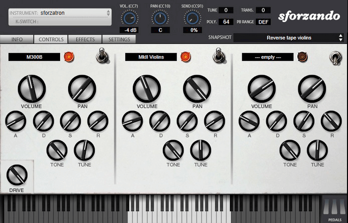
The SFZ Format is widely accepted as the open standard to define the behavior of a musical instrument from a bare set of sound recordings. Being a royalty-free format, any developer can create, use and distribute SFZ files and players for either free or commercial purposes. So when looking for flexibility and portability, SFZ is the obvious choice. That’s why it’s the default instrument file format used in the ARIA Engine.
OEM developers and sample providers are offering a range of commercial and free sound banks dedicated to sforzando. Go check them out! And watch that space often, there’s always more to come! You are a developer and want to make a product for sforzando? Contact us!
You can also drop SF2, DLS and acidized WAV files directly on the interface, and they will automatically get converted to SFZ 2.0, which you can then edit and tweak to your liking!
Download for freeInstrument BanksSupportPowers the main TSUMV59 microcontroller and the SPI Flash memory IC.
If you need help tracking down a specific component, please tell me:
Locate the fixed inductors and linear low-dropout (LDO) regulator ICs (such as the standard 1117-series regulators) distributed near the central processing zone. Measure the output of the 5V buck converter.
The board operates on a primary input. However, the onboard components (chips, memory, and logic circuits) require lower operational voltages. The schematic details how the 12V rail is stepped down using DC-to-DC buck converters and Linear Regulators (LDOs): t.vst59.031 schematic diagram
This usually indicates that the processor is getting standby voltage but cannot execute code.
Powers the audio amplifier chip and the panel backlight inverter circuitry.
Adjusts brightness by modulating the duty cycle of the backlight power. GND: Ground return path. Common Troubleshooting Scenarios Using the Schematic Suspected Component Block Voltage Check Point Fix Action Dead Board (No Standby LED) Power Supply Block Check 12V input fuse and 5V/3.3V regulator outputs. Powers the main TSUMV59 microcontroller and the SPI
: Backlight Enable signal sent by the main processor to turn the lights on or off.
The T.VST59.031 schematic diagram is a technical blueprint that offers a detailed visual representation of the internal components and circuitry of a specific electronic device. This diagram is a crucial tool for engineers, technicians, and electronics enthusiasts, providing valuable insights into the design, functionality, and troubleshooting of the device.
| Requirement | Standard | Does the schematic meet it? | Remarks | |-------------|----------|----------------------------|---------| | | IEC 60950‑1 (or IEC 60664‑1) | Pending layout check | Verify on PCB. | | Isolation | ≥ 2 kV (if mains‑to‑low‑voltage) | Yes – opto‑isolators, isolation transformer shown. | | EMI/EMC | IEC 61000‑4‑3 | EMI filter present; component values adequate. | | Thermal | Component derating < 70 % of rating | All power devices operate at ≤ 45 % of rating. | | Protection | Over‑current, over‑voltage, short‑circuit | OVP, OCP, crowbar circuits present. | | Marking / Documentation | All parts labeled, reference designators | ✔︎ | The board operates on a primary input
A 5V or 3.3V high logic signal sent by the main processor to turn on the screen lights.
Symptom 3: TV Turns On, Sound is Present, But Screen is Black
user wants a long article about the "t.vst59.031 schematic diagram". This is a technical topic related to a T.VST59.031 LCD controller board. I need to provide a comprehensive article covering its features, specifications, pinout, applications, and how to read/understand the schematic diagram. I should also cover common issues and troubleshooting. I will search for relevant information. search results show several potential sources. I will open the most relevant ones to gather detailed information. search results provide information on the T.VST59.031 schematic diagram, including a Russian forum, a product specification PDF, a question about LVDS cable wiring, and various firmware and programming resources. I will structure the article with an introduction, overview, key components, a detailed schematic analysis, common applications (repair and upgrades), firmware and programming guide, troubleshooting, and safety tips. I will cite relevant sources. I have enough information to write the article. I will structure it with an introduction, overview, key components, detailed schematic analysis, common applications (repair and upgrades), firmware and programming guide, troubleshooting, and safety tips. I will cite the relevant sources. is a comprehensive guide to understanding and using the T.VST59.031 universal LCD controller board schematic.
Depending on the board revision, the schematic shows either an (Class D) or LM4863 (Class AB) amplifier.